- All
- Product Name
- Product Keyword
- Product Model
- Product Summary
- Product Description
- Multi Field Search

Views: 0 Author: Site Editor Publish Time: 2026-09-15 Origin: Site


In precision engineering and quality assurance (QA), using uncalibrated measurement tools introduces severe operational risks. Even a microscopic deviation compromises product integrity. Addressing these initial discrepancies is not merely a technical fix. It establishes a required baseline for reliable, compliant manufacturing processes. When operators ignore misaligned jaws, they risk passing out-of-spec components down the production line. This guide outlines exactly how you can manage these calibration challenges. We will cover identifying the initial deviations visually. You will learn to apply corrective formulas effectively during daily operations. Finally, we explore how to determine when aging tooling requires replacement or standardization. Mastering these steps ensures your measurement protocols remain accurate, repeatable, and deeply trustworthy.
Cost of Inaccuracy: Uncorrected zero error leads to compounded QA failures and out-of-spec production.
Identification Protocol: Determining positive versus negative zero error requires a standardized visual check of the main and vernier scales.
Correction Logic: Accurate measurements rely on a strict adherence to the formula: True Reading = Measured Reading - (Zero Error).
Tooling Decisions: Persistent mechanical zero error is a key indicator that a facility must evaluate repairing existing tools versus upgrading to digital, auto-calibrating alternatives.
Micro-millimeter variances cascade rapidly into macro-level defects. You might measure a critical engine component incorrectly by a tiny fraction. This single mistake often leads to complete part rejection. It can also cause severe compliance audit failures during quality checks. Modern manufacturing leaves no room for ambiguous dimensions. When teams fail to verify their baselines, entire production batches face expensive scrapping.
Mechanical realities frequently introduce these alignment issues over time. Jaw wear happens naturally through repetitive, daily use on hard materials. Environmental temperature fluctuations also cause the metal components to expand or contract. Improper storage conditions further damage the delicate sliding mechanisms. Dropping the instrument even once can permanently misalign the measuring faces. Operators must understand these physical vulnerabilities.
Reliable measurement protocols require strict success criteria. First, you need high repeatability across different shifts and users. Second, your measurements must maintain traceability to accepted industry standards. Third, operator consistency remains vital for overall quality assurance. We must train teams to handle tools uniformly. They should apply the same pressure and read the scales from the same angle. Standardizing these human elements minimizes unexpected dimensional deviations.
Before checking anything, you must standardize your pre-check routine. Skipping these preparation steps often generates false readings. Precision instruments require a controlled environment for accurate evaluation. You should implement the following mandatory steps before every shift.
Wipe the measuring faces clean using a lint-free cloth.
Remove any residual oil, coolant, or metallic dust.
Close the jaws gently using the thumb wheel.
Apply correct closing pressure without forcing the metal together.
Lock the instrument lightly if required for the visual check.
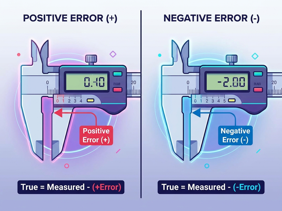
Positive deviations occur under specific visual conditions. You will notice the zero mark on the sliding scale rests to the right of the main scale zero. This means the instrument reads a value greater than zero when the jaws are completely shut. If you ignore this, every subsequent measurement will be artificially inflated.
Conversely, negative deviations present a different visual cue. The zero mark on the sliding scale rests slightly to the left of the main scale zero. This indicates the instrument reads below zero when fully closed. Failing to catch this results in continuously underestimating the true dimensions of your workpieces.
When quantifying this exact deviation, rely on the specific markings of a vernier caliper metric scale. Look closely at the divisions. Find the exact mark on the sliding scale aligning perfectly alongside a mark on the main scale. Multiply this specific division number by the instrument's least count. This calculation gives you the precise numerical value of the deviation.
Accurate results depend entirely on universal formula application. You must memorize and apply the following equation: True Reading = Measured Reading - (Zero Error). You always subtract the baseline deviation. However, you must include its mathematical sign (positive or negative) during the calculation. This simple rule prevents catastrophic machining errors.
Let us execute the math for a positive scenario. Suppose your instrument shows a +0.02 mm deviation at rest. You measure a steel rod at 15.05 mm. You subtract the positive value to prevent overestimation. The math looks like this: 15.05 mm - (+0.02 mm) = 15.03 mm. Your true dimension is 15.03 mm.
Now consider a negative scenario. Imagine the instrument shows a -0.03 mm deviation. You measure another component at 20.10 mm. You subtract the negative value. Subtracting a negative effectively means you are adding it. This prevents underestimation. The math is: 20.10 mm - (-0.03 mm) = 20.13 mm. We successfully corrected the hidden deficit.
Operator education serves as the final defense against bad data. You must connect this correction math directly to the fundamentals of how to read a vernier caliper. Trainees often struggle initially. Sometimes they add when they should subtract. Sometimes they double-compensate because they get confused by the negative signs. Regular practice builds confidence. When operators master identifying vernier caliper zero error, they protect the entire production chain from costly scrap.
Scenario | Initial Baseline State | Raw Component Reading | Applied Formula | Final True Dimension |
|---|---|---|---|---|
Positive Error | +0.04 mm | 50.20 mm | 50.20 - (+0.04) | 50.16 mm |
Negative Error | -0.02 mm | 12.50 mm | 12.50 - (-0.02) | 12.52 mm |
Perfect Calibration | 0.00 mm | 35.15 mm | 35.15 - (0.00) | 35.15 mm |
Assessing tool lifespan requires brutal honesty from QA managers. Manual mathematical corrections work perfectly for occasional checks. However, they become too risky for high-volume production lines. When operators measure hundreds of parts daily, mental fatigue sets in. A tired machinist will eventually miscalculate a negative adjustment. When manual baseline correction consumes too much time, you cross the threshold where upgrading becomes necessary.
Evaluating traditional versus digital models involves several dimensions. Features directly impact your outcomes. Digital models offer instant-zeroing capabilities. You press a button, and the screen calibrates instantly. Traditional instruments force you to perform manual mathematical corrections every single time. Digital tools remove human calculation mistakes entirely.
Scalability heavily favors modern equipment. Consider the speed of measurement across large batch testing. Digital screens provide immediate readouts. Traditional scales require careful visual alignment under good lighting. When evaluating compliance, modern tools win easily. Data-logging capabilities allow direct export to QA software. This creates a perfect paper trail for ISO reporting. Traditional logging relies on handwritten notes.
Use clear shortlisting logic when selecting replacement tools. Look for IP67 ratings to ensure coolant and dust resistance on harsh shop floors. Demand certified calibration certificates from the manufacturer. Evaluate battery life and data-output ports. Do not simply buy the cheapest option. Invest in equipment matching your specific environmental hazards.
Evaluation Category | Traditional Manual Tooling | Digital Measurement Tooling |
|---|---|---|
Zeroing Method | Manual mathematical formula application | One-touch electronic calibration button |
Batch Testing Speed | Slow; requires visual alignment and calculation | Fast; immediate visual readout on screen |
Compliance & Logging | Manual handwriting; high risk of transcription error | Automated data export; seamless ISO traceability |
Environmental Durability | Extremely high; no electronics to fail | Requires IP67 rating for coolant/dust protection |
Implementation realities often involve fighting human nature. Addressing the friction of enforcing manual checks remains your biggest hurdle. Operators rush to begin their shifts. They often skip verifying their baselines to save time. You must integrate these checks smoothly into the daily workflow. Make the verification process as painless as possible.
Risk mitigation requires external validation. We highly recommend protocols for periodic third-party calibration. Internal teams can develop blind spots. An external metrology lab verifies that your internal checks remain accurate. They provide master gauge blocks and issue formal certificates. This external audit keeps your internal standards honest and rigorous.
Adoption and training determine your long-term success. Outline a simple, verifiable training checklist for new machinists. Ensure standard operating procedures (SOPs) are followed without deviation. Good checklists prevent bad habits from forming.
Provide dedicated master gauge blocks at every workstation.
Mandate a documented baseline verification before the morning shift starts.
Require a secondary check after dropping or bumping the instrument.
Log all significant deviations in a shared maintenance database.
Audit operator technique monthly to ensure proper closing pressure.
Checking for initial baseline deviations remains a non-negotiable step in precision quality control. Skipping this crucial visual inspection compromises your entire production batch. Even the most advanced manufacturing facilities rely on these fundamental measurement principles.
You must embrace a strict decision matrix. Train your staff extensively to calculate and correct minor discrepancies accurately. However, you must also systematically replace tools suffering from severe mechanical wear. Persistent jaw misalignment introduces unacceptable operational risks. Upgrading to modern digital solutions often proves safer for high-volume environments.
Take action immediately. Audit your current QA measurement tools today. Establish a standardized, daily pre-measurement verification policy across all shifts. Your commitment to these baseline checks guarantees long-term product integrity and unwavering client trust.
A: Mechanical wear represents the primary cause. Repetitive sliding wears down the metal jaws. Dropping the instrument misaligns the measuring faces instantly. Additionally, overtightening the locking screw frequently warps the delicate sliding carriage, causing permanent baseline shifts.
A: You can apply mathematical correction formulas to adjust your final readings. However, physically repairing the instrument requires professional jaw re-grinding. This machining process is expensive and rarely cost-effective compared to simply purchasing a replacement unit.
A: Frequency depends heavily on usage volume. We recommend daily verification against a gauge block before every shift starts. High-precision industries should also mandate formal, documented calibration by a certified third-party laboratory at least once annually.
A: No. While digital calipers feature a convenient calibration button, physical jaw wear still occurs. If the jaws do not close parallel, the electronic zero means nothing. You still require routine physical verification using master gauge blocks to ensure true accuracy.